

|
|
|
|
 |

|
 |
BMW Garage | BMW Meets | Register | Today's Posts | Search |
 |

|
BMW 3-Series (E90 E92) Forum
>
Pre-LCI E92 Boot/Trunk Release Switch Retrofit
|
 |
| 06-12-2020, 10:32 AM | #1 |
|
First Lieutenant
 
46
Rep 355
Posts |
Pre-LCI E92 Boot/Trunk Release Switch Retrofit
Hi All,
Been doing some research and apparently it is possible to retrofit a boot release switch (right above the OBD port) and its a very easy low cost retrofit, as 3 wires need connecting, 1 for +ve, 1 for the locking access unit and one for the lighting unit (to illuminate the switch), as per post 15 in this thread: https://www.e90post.com/forums/showthread.php?t=504404 Can anybody provide a wiring diagram or instructions on how to wire this up please? I can find a switch for £15 on eBay but not sure about the wiring loom part number to connect the switch. I can do with this retrofit as there is no way to release the boot - the key button does not work when in the slot and engine is ON. The unlock button only unlocks the boot, it doesn't release it. Thanks a lot. |
| 06-14-2020, 09:43 AM | #4 |
|
eBay Special

3078
Rep 3,031
Posts
Drives: E90 330xi
Join Date: Feb 2018
Location: Western Slope, Colorado
|
You're telling me BMW deleted the boot release switch? Ridiculous lol
__________________
Common sense is a flower that does not bloom in everyone's garden
|
|
Appreciate
0
|
| 06-14-2020, 03:58 PM | #5 |
|
First Lieutenant
46
Rep 355
Posts |
https://f30.bimmerpost.com/forums/sh....php?t=1132318
I found the above thread but its for the F30, just wondering whether the diagrams in post number 8 could be useful, assuming it is a similar set up in the E9x models. AND, I have found another thread below... This person was/is selling the complete kit including the switch and wiring loom etc for £35. Not sure if this person is still selling it but I will try to contact this person and will update on here. https://forums.m3cutters.co.uk/threa...t-kits.129728/ |
|
Appreciate
0
|
| 06-14-2020, 04:15 PM | #6 | |
|
Private First Class

45
Rep 158
Posts
Drives: 2011 328i
Join Date: May 2008
Location: Attleboro, MA
|
Quote:
|
|
|
Appreciate
0
|
| 06-14-2020, 04:32 PM | #7 | ||
|
eBay Special
3078
Rep 3,031
Posts
Drives: E90 330xi
Join Date: Feb 2018
Location: Western Slope, Colorado
|
Quote:
But yeah the trunk lock is for valet, I use it when I have to take my car to a shop
__________________
Common sense is a flower that does not bloom in everyone's garden
|
||
|
Appreciate
0
|
| 06-16-2020, 03:44 PM | #8 | |
|
First Lieutenant
46
Rep 355
Posts |
Quote:
This kit works both with and without the key in the car, engine on/off... Its £40 but worth while IMO given there is not much information on how to wire it up and the fact that a custom harness/connectors are also needed. I have agreed to the price and will update you all once received and installed. Hope this helps. |
|
|
Appreciate
0
|
| 07-01-2020, 03:39 AM | #9 |
|
First Lieutenant
46
Rep 355
Posts |
I've received the kit and its pretty straight forward but not a kit I could make my self as I would have needed to source a customer harness for the switch, and a custom pin for the wire to connect to the CAS connector.
Connection is simply the following: The harness connector (which goes into the switch) has 3 wires coming out: One wire is for the ground One wire is for the backlight/illumination for the button when lights are switched on ^^ These two wires can basically be connected using scotch locks or doing a bit of soldering The last wire, as mentioned at the start, is the one which goes into slot 39 of the CAS. This wire has the correct pin crimped on it, as part of the kit by 'ccfj' on M3 Cutters forum. The pin basically needs to be pushed into slot 39 of the CAS harness. Its has simple a that. Although, I would personally remove the battery before taking the CAS harness off as the CAS is a critical ECU of the car... |
|
Appreciate
0
|
| 08-23-2021, 03:33 PM | #10 | |
|
Private
 15
Rep 78
Posts |
Quote:
I've found the wiring diagram stating that PIN 3 of the Boot Release switch goes to PIN 39 on the CAS (below - look for S204) 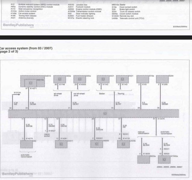 But do we know where the lighting pin goes? I presume there is a ground comb nearby that I can tap into - but is that PIN 1 or 2 switch-side? Any help would be great. EDIT; found the wiring diagram.  Boot Release Switch PIN 2 (0.35mm2 wiring - grey/red) to X908 - this is for the internal illumination PIN 3 (0.35mm2 wiring - grey/brown) to PIN 39 on X13376 (CAS) PIN 4 (0.35mm2 wiring - brown/white) to X1108 - earth I'm unsure what X908 is, I think it's a junction of some description down in the drivers footwell. Having checked further wiring diagrams, I'm going to trace PIN 48 from X14261 on the FRM to this location, and go from there. ALTERNATIVELY, if like me, you have a switch with only PINS 1-3. PIN 1 (0.35mm2 wiring - grey/red) to X1019 - this is for the internal illumination PIN 2 (0.35mm2 wiring - brown) to X1108 - earth PIN 3 (0.35mm2 wiring - green/black) to PIN 39 on X13376 (CAS)  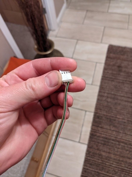 Done  Last edited by Nickdot; 08-23-2021 at 05:14 PM.. |
|
|
Appreciate
0
|
| 01-30-2023, 01:03 PM | #11 | |
|
Private First Class

142
Rep 115
Posts |
Quote:
https://www.ebay.co.uk/itm/325227771...mis&media=COPY
__________________
If it?s Standard Modify it
|
|
|
Appreciate
0
|
| 08-15-2023, 05:14 AM | #12 |
|
New Member
3
Rep 14
Posts |
Thread revival!
I have plugged into pin 39 of cas, I am struggling to find the 12v and the ground near the drivers footwell. Any tips or clues? Also, should the switch work with just the pin in 39 or does it require all three cables to work? Thanks for any help in advance |
|
Appreciate
0
|
| 08-18-2023, 02:37 AM | #13 |
|
New Member
3
Rep 14
Posts |
For future users, the easy way to do this is to plug into the driver footwell module, which is behind the OBD port.
Unscrew the engin open latch, unscrew the second screw hiden by it. The driver footwell module is right there. The first visible connector is the X14259, facing towards the driver. Pin 5 of this connector is ground Pin 21 is instrument lighting Easiest install, no need to remove driver footwell or rout anywhere far away, this is right behind the switch itself. Remove trim above driver footwell for more room. |
|
Appreciate
0
|
| 10-08-2023, 06:46 AM | #14 | |
|
Registered
0
Rep 2
Posts |
When you fitted the earth and lighting wires, did you just re-pin the existing earth and illumination wires that are already installed in the X14259? Thanks
Quote:
|
|
|
Appreciate
0
|
 |
| Bookmarks |
|
|


